Disassembly of the HP LaserJet IIP printer
Introduction
The HP LaserJet IIP printer was introduced in about 1989. My wife bought ours in about 1992. It has been a very solid and reliable printer over the years, though I have had to replace some parts: rollers, fuser, and a couple of controller boards.
Most recently it was displaying the "50 needs service" message. This indicates that the fuser does not come up to temperature within a certain time. I started out by replacing the fuser lamp (which did have a crack in the insulation at the end), but this did not fix the problem. I ended up replacing both the inlet power supply and the DC controller PCB. It is now as good as new.
As I was doing these repairs, (and since I had to order more than one replacement part) I thought I would document the repair process, taking lots of pictures along the way. Disassembly is actually not that difficult.
2023 note: I used to use (back in 2010) www.fixyourownprinter.com to get parts, and they provided great disassembly instructions, both written, and video, along with the replacement parts. However, they no longer seems to be around. A Google search will find several other suppliers, with varying amounts of parts.
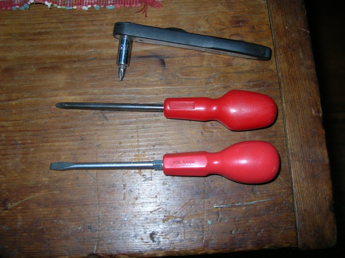
Tools needed:
- Philips screwdriver
- small compact Philips screwdriver, same size tip as above, or ratchet wrench like I used (for getting into small spaces)
- flat blade screwdriver for gently prising open clips (or good fingernails!)
Screwdrivers can be magnetized for convenience.
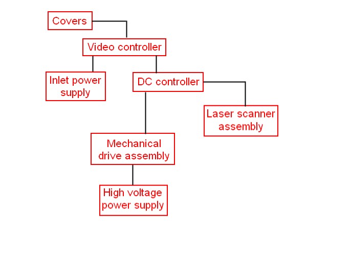
Disassembly flowchart
Here is a flowchart showing the order of dismantling items. This is an image map, so you can click on individual items to jump straight to its disassembly instructions. Some parts are not shown here, eg. the rollers. I will update this if/when the rollers need to be replaced.
Starting disassembly - removing the covers
Disconnect power from mains first, and remove font cartridge if present.
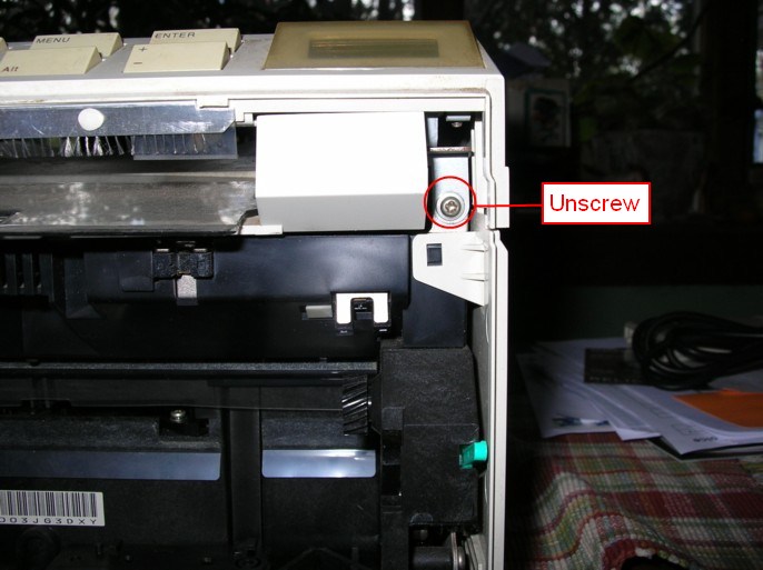
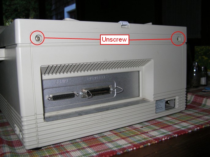
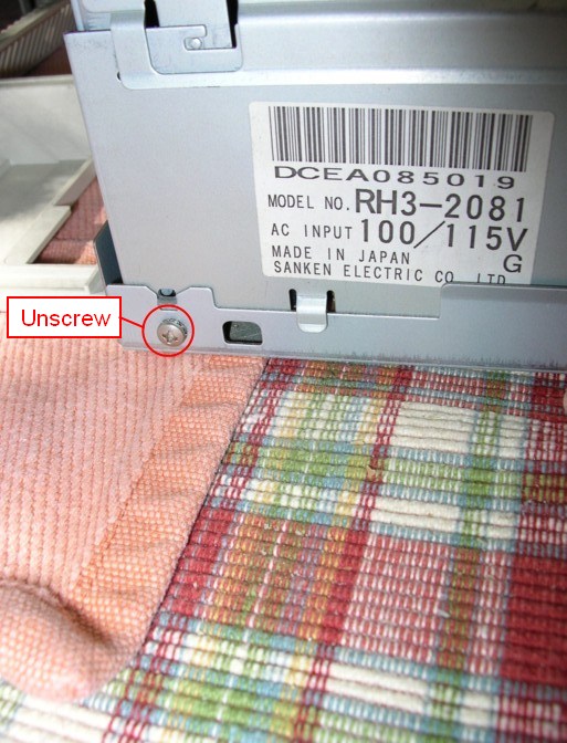
Open front door and remove toner cartridge. Place in safe place, away from bright light and heat. Undo 2 screws, one at the left:

and one at the right.
Unscrew rear cover at the 2 screws, (they do not come completely out).
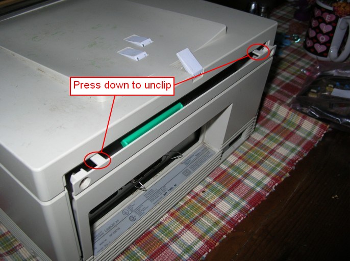
Note the two tabs that hold the cover in place. Press to release the cover and fold it down.
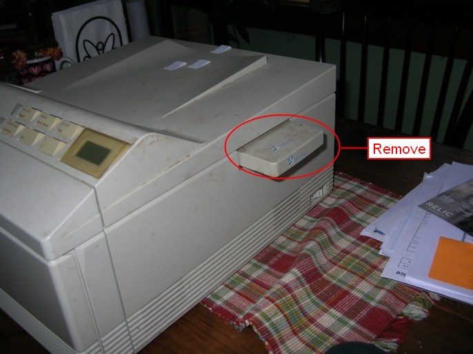
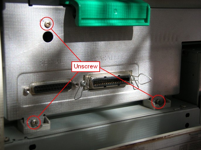
Unscrew I/O bracket (3 screws) and pull out using green handle. Place aside.
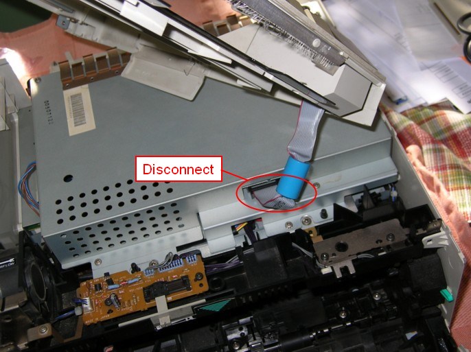
Lift up top cover, and disconnect ribbon cable from video controller assembly. Place aside.
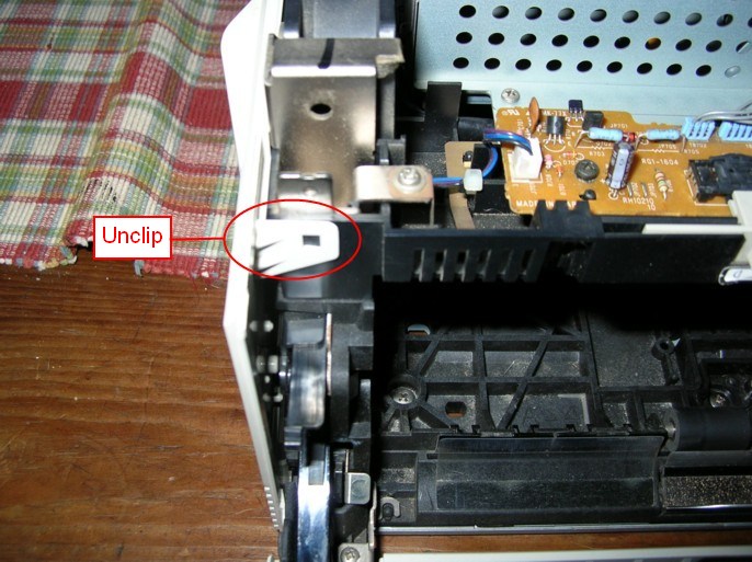
Remove side cover panels by releasing clips, one at top left:
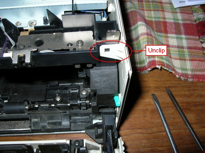
and the other at top right:
Fold both side cover panels down and away from printer. Place aside.
Remove 3 screws from rear cover plate, and place aside.
Video controller
With covers removed, remove cable from connector on left side of video controller assembly.
Remove 4 screws and lift off the video controller assembly. Place aside.
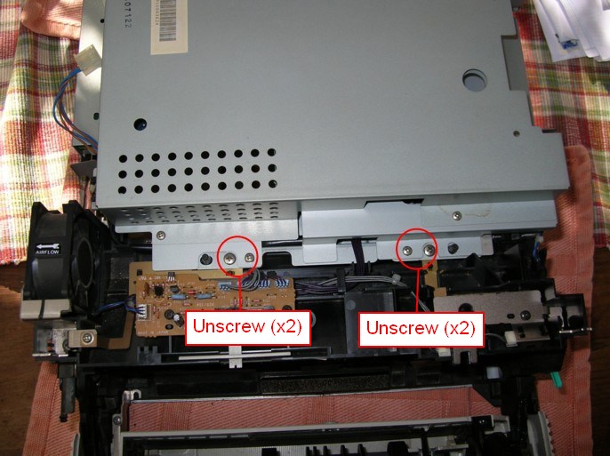
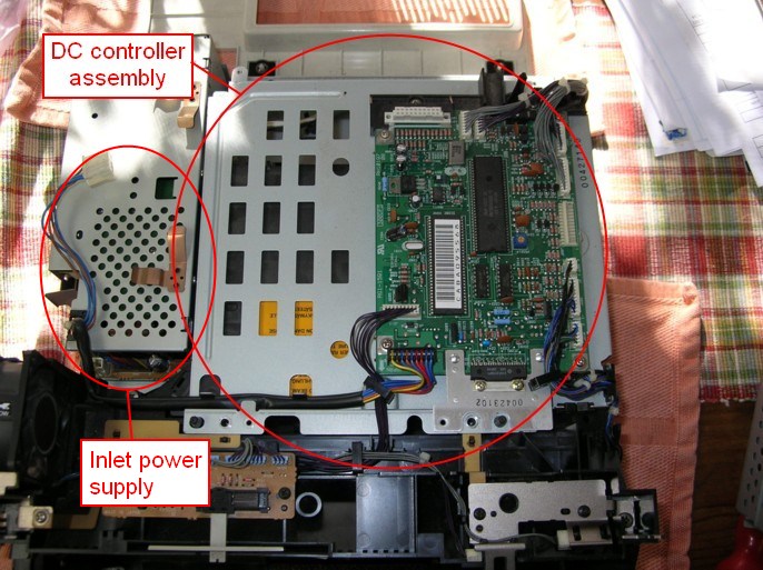
This exposes the DC controller assembly with its PCB, and the inlet power supply. Either one can be removed without removing the other, depending on what needs to be replaced: see DC controller/PCB, or inlet power supply.
DC Controller PCB
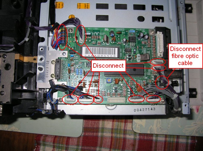
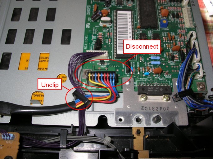
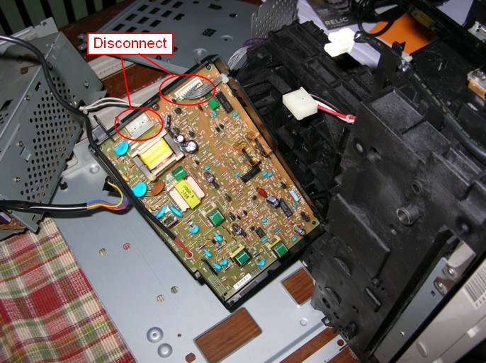
To remove just the DC controller PCB, disconnect all the cables from their connectors. Be careful when disconnecting the fibre optic cable. See here to remove the entire DC controller assembly.
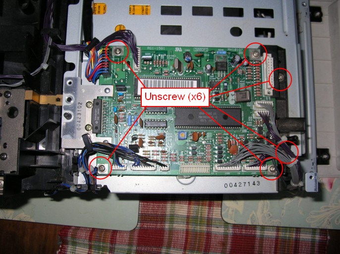
Remove the 4 screws holding the PCB down, and the two screws holding the black retaining bracket (one of these is hidden in the picture).
Inlet power supply
The inlet power supply can be removed with 3 screws: outside rear left:
...inside rear right:
...and inside front left. Disconnect plug from connector:
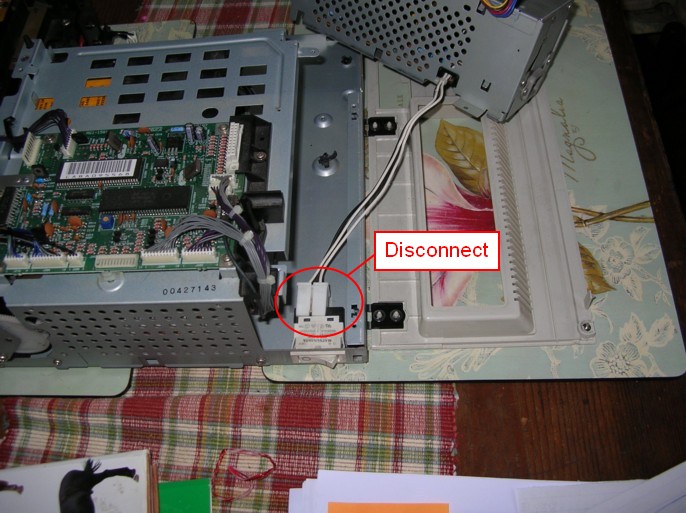
To remove completely, disconnect the cable going to the main switch:
and the cable going to the DC controller PCB:
DC controller assembly
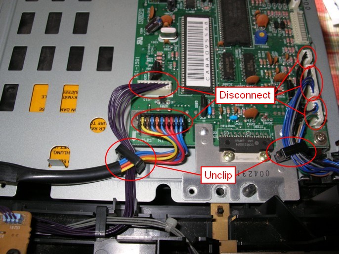
To remove the DC controller assembly, it is not necessary to remove the DC controller PCB. Just remove the lower left connectors (x2), and the lower right connectors (x3) on the DC controller PCB. Unclip the 2 cable clamps holding these wires.
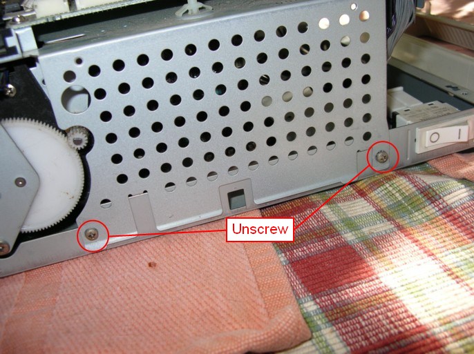
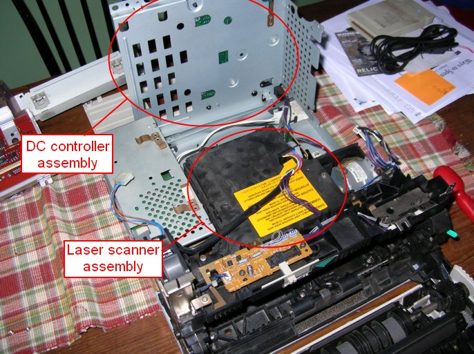
Remove the 2 screws at the side and the whole DC controller assembly can be lifted out of the way and placed on end. No need to disconnect everything.
This exposes the laser scanner assembly. See below if you want to open this up, otherwise proceed to remove the main mechanical assembly, and high voltage power supply):
Mechanical drive
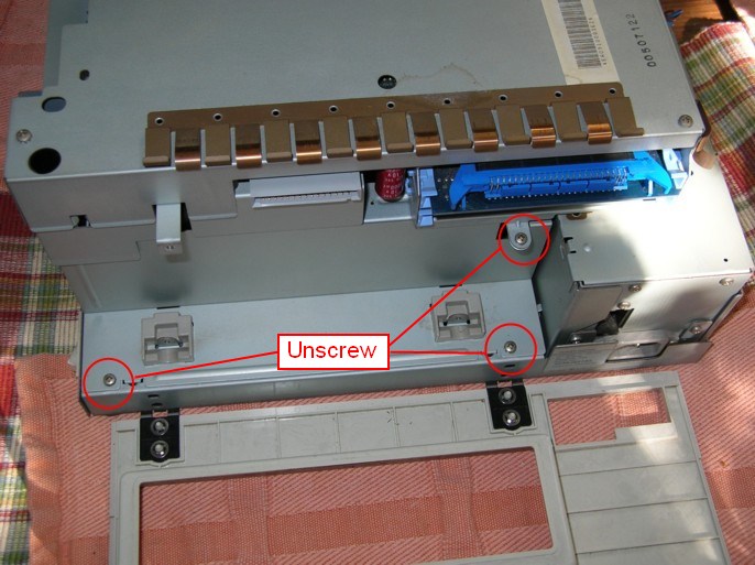
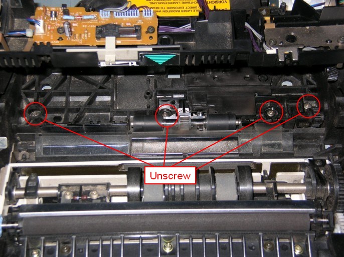
Remove 4 screws from the front roller assembly (here's where you'll need that compact screwdriver or wrench).
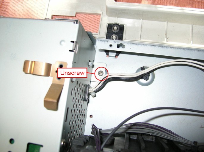
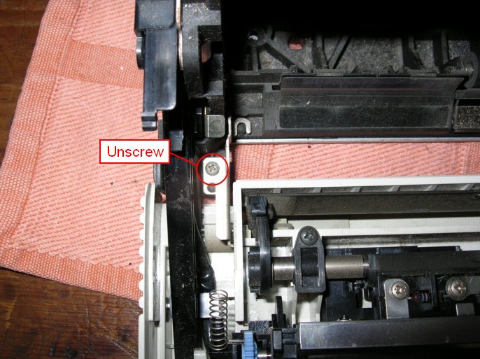
To separate the main mechanical drive assembly from the metal base of the printer, remove screw at inside left...
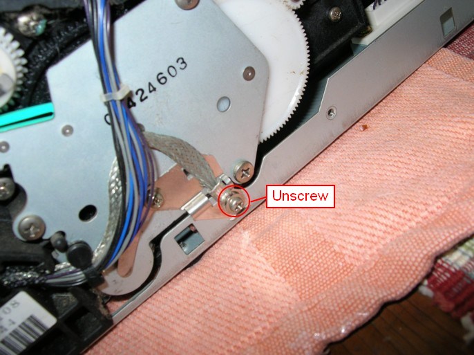
...at outside right:
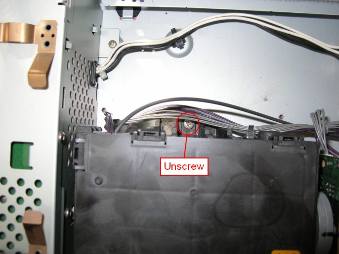
...and at the inside rear center:
Now you can lift up the entire mechanical drive assembly away from the metal base of the printer. Here it is standing on end, with the base of the high voltage power supply assembly visible:
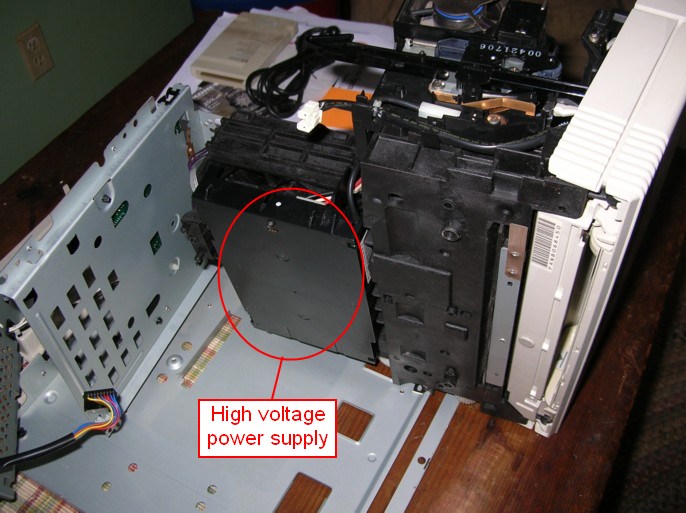
...and here with the high voltage power supply swung around to expose the cables (I had already disconnected one of the cables when I took this picture):
High voltage power supply
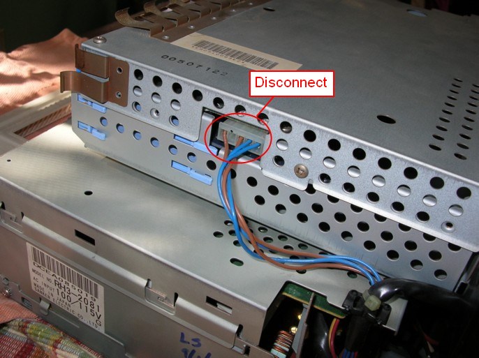
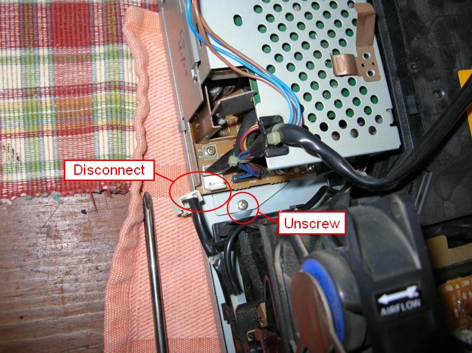
To remove the high voltage power supply, disconnect the 2 cables attached to the main circuit board:
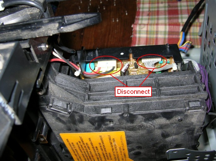
...and the one near the fan:
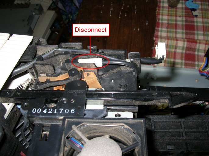
Laser scanner assembly
After removing the DC controller assembly and exposing the scanner assembly cover, remove the screw on the right hand side, and undo the clips:
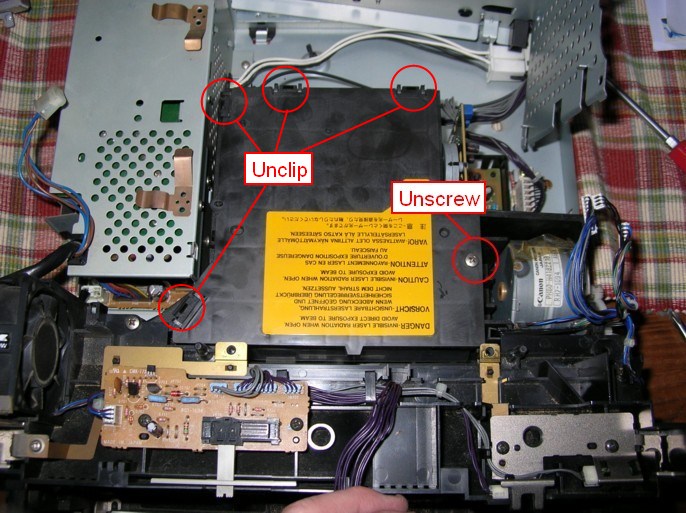
...and lift off the cover:
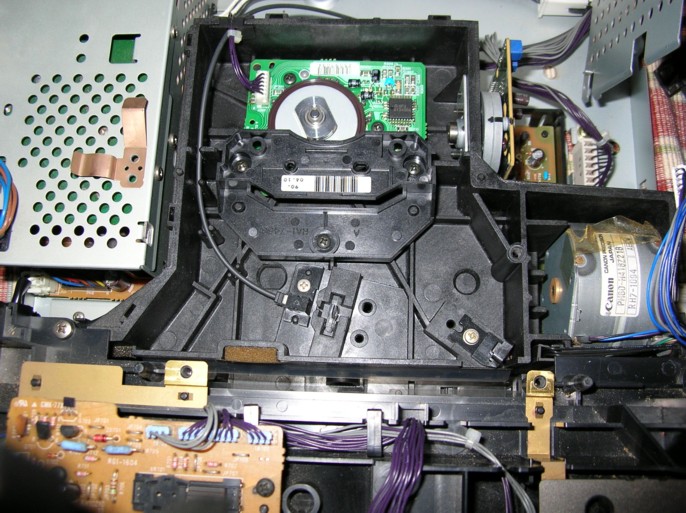
From here, you can remove the circuit board and the scanner motor. I have no pictures for these steps, even though I did replace the scanner motor a couple of years ago.
Reassembly
To reassemble, follow the above steps in the reverse order. Don't lose any screws!
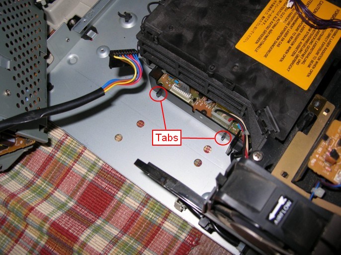
Note that when replacing the high voltage power supply, there are tabs on the right side that fit into holes in the metal printer base (one is hidden by the connector):
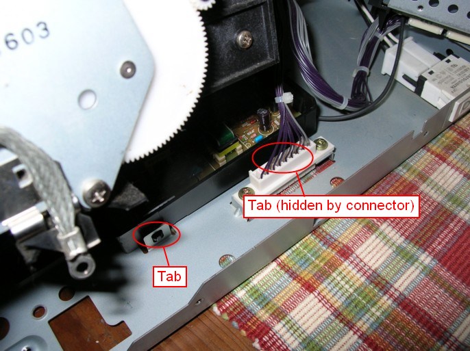
and the tabs on the left side are held down by the inlet power supply module.
This entire www.gatcombe.com website is Copyright © Chris and Danelle Gatcombe